FRED DOUGHERTY’S DUCT DESIGN PAGE
This page updated February 18, 2012
FRED DOUGHERTY’S DUCT DESIGN PAGE
This page updated February 18, 2012
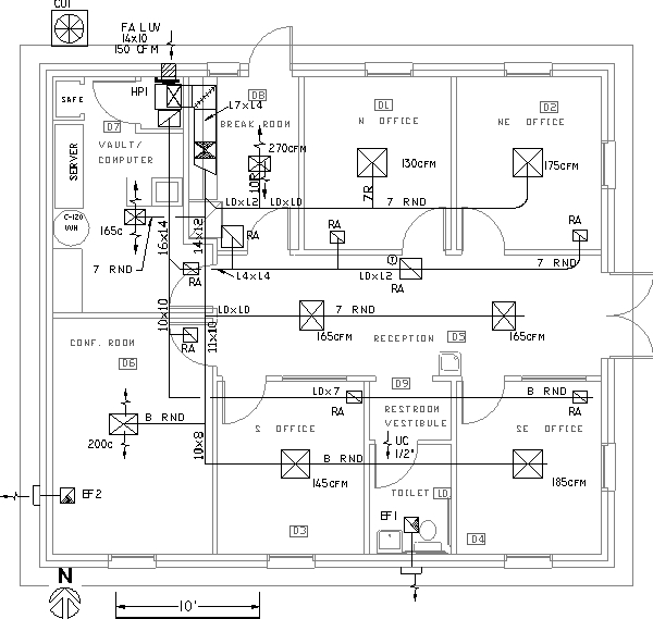
The graphic above is an AutoCAD layout of a small office air conditioning system. This graphic is reproduced from Chapter 12 of my book, where the principles of duct design and sizing are explained. Prominent on this layout are the dark lines that represent supply air ducts and the green lines that represent return air ducts. Numbers indicate duct dimensions. For those unfamiliar with drawing convention of duct layout, round duct sizes are indicated as RND, and rectangular duct sizes have two numbers as 12x10, where the first number is the dimension in the plane of the layout. Thus 12x10 denotes a duct with inside dimensions of 12 inches wide and 10 inches high. If an elevation (side view) of this duct is shown, the dimensions would read 10x12.
On this page I am making available an Excel workbook I created to assist me with determining duct size and fan external static pressure requirements. A paper that explains the workbook and how the macros were developed will be found here.
Since I initially created the spread sheet, I have incorporated some improvements to make it easier to use and understand. There is now an input sheet where the user can input all of the needed data. Also, the iteration method of performing the original rough duct sizing has been improved and no longer requires running a macro. Instead, User Defined Functions (UDFs) have been incorporated so that the rough sizing is performed automatically and instantly when the macro "friction factor" is run. The input sheet was developed by a Mr. Lee, whose full name I have misplaced. The UDFs were created by Tom Lester.
The spread sheet described in the article above can be downloaded by left clicking here. Directions for inputs and running the macro are on sheet 1 of the workbook. Click here for additional notes to on using the spread sheet. Contact me if you have questions, comments, or suggestions.