 Lightning Protection
by Design
Lightning protection procurement tends to follow the same
procurement
strategy that is followed when purchasing life insurance; you buy as
much
as you feel you need or as much as your budget will allow.
Therefore there are two factors guiding the designer when
considering
lightning protection: cost and need. Both factors are legitimate design
considerations. Since bridges are usually public property, budget is
usually
beyond the control of the designer and must be programmed by a
governmental
administrator for projects specific to bridge structures. Need,
however,
is a factor that requires technical consideration by a qualified
lightning
protection engineer. This article will focus on the technical
considerations
of lightning protection engineering specific relative to concrete
bridge
structures.
The example I will use is the upgrade of the lightning protection
system
for the Sunshine Skyway Bridge. Lightning protection design is based on
the laws of Physics and site specific factors. Therefore, any design
must
consider location and the structure's risk to lightning damage to
either
the structure or the electronic and electrical systems that control
bridge
lightning and traffic control devices. Florida is a high-incident area
for lightning. In addition, lightning currents average six times the
national
average for lightning currents. Design requirements must start with the
need assessment and a need assessment must include location,
construction
and appurtenances.
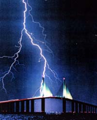
Figure 2
The original lightning protection system was developed during the
architectural
design and construction of the structure. This design was based on a
design
found in the Lightning Protection Institute (LPI) design guide for
smoke
stacks. Air terminals (lightning rods) were installed in each of the
four
corners of the two cable stay towers and two separate ground conductors
were installed vertically down opposite corners of each of the towers
and
continued down to the salt water line. The height of the cable stay
towers
can be seen in the photo in Figure 2 and represents approximately half
the distance to the water where the effective ground termination for
this
system is located.
Bridge Maintenance contacted my office and explained that damage to
the structure was found after thunderstorms. This damage varied from
damaged
surveillance cameras to tripped circuit breakers and pieces of concrete
found on the bridge that clearly came from the structure. The pieces of
concrete concerned me the most. Some pieces weighed about 50 pounds and
if pieces of such mass were to fall from the towers, the risk to life
and
property quickly was recognized and the Department immediately approved
a rigorous research effort to determine the most effective, cost
effective
and timely design as well as budgeted funds to construct the upgrade to
the existing protection system.
A site survey was immediately conducted to determine the existing
condition
of the lightning protection system and collect data that could be used
to develop a computer simulation model (CADD) of the existing system.
The
model selected was a Pspice mathematical nodal analysis model which
offered
the engineer many points to insert the lightning attachment forcing
function
and reiterative "what-if" capabilities that were fast and cost
effective.
The output of the model was a graphical display of voltage and current
over time between any two nodes in the system.
This model revealed that the existing system was very inefficient
and
could be dangerous to maintenance personnel during a storm. The
inefficiency
of the system caused large voltages to be developed along the
electrical
conductors that connected the air terminals to the ground 431 feet
below
at the water line . The large potentials developed could reach more
than
a million volts in areas were maintenance personnel regularly worked.
In
addition, and less predictable but far more ominous was that the large
voltages also indicated that the system was acting as a restriction to
the lightning discharge path.
The laws of Physics clearly supports the one-time commercial
statement
that "It's not nice to fool Mother Nature". The delays indicated by the
large voltages also indicated that the larger the discharge, the more
likely
that alternate paths would be used to fulfill the need to complete the
discharge of energy between cloud and ground. Lightning protection
design
is based on knowing where the lightning strikes (the attachment) and if
the system designed to control the attachment and conduct attachment
currents
harmlessly away is insufficient to the task, alternative attachment
points
and the path or paths taken by attachments to parts of the structure
that
is not part of the lightning protection system or overload currents
become
unpredictable and potentially dangerous. Ultimately, a rigorous
research
effort was approved to determine the most cost effective and capable
design
for an upgrade of the existing system.
This design took advantage of the geometry of the bridge and the
Tampa
Bay water salt content as well as the design of the most efficient and
protective electrical system to attract, control and manage large
lightning
discharge currents. The bridge roadway towers 175 feet above the water
in the center of the main span and the two cable stay towers exceed 431
feet above the water (MSL). The view from the top of the towers as seen
in Figure 3 gives perspective to the task.
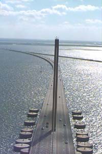
Figure 3
There are two towers, each supporting 21 continuous cable stays at
their apex. The cable stays are connected to adjustable anchors in a
line
of 21 anchor arrays radiating away from each tower longitudinally along
the centerline of the main span. These cable stays are multi-stranded
steel
cables wrapped in steel and covered by a round steel case (and qualify
as excellent lightning attractors). The upgrade design included
grounding
the cable stays at the adjustable anchors shown in Figure 4. The cable
stays are continuous and travel through a saddle at integral levels in
the towers to maintain a constant support angle that maximizes the
vertical
and horizontal vectors required by the design. Access to the cable
stays
at the saddles was not possible because the saddles were concrete and
surrounded
each cable. Therefore the only metallic access to the cable stays that
facilitated an adequate mechanical and electrical connection was inside
the main span structure at the adjustable anchors.
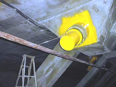
Figure 4
Figure 4 is a photo of the adjustable anchor connection (called a
trumpet)
and the horizontal conductor that connects the anchors together. This
conductor
also continues down to the water line and completes the circuit to
ground
using the salt water in the bay. The conductors are flat and direct the
lightning currents along straight paths and smooth bends. No 90 bends,
sharp turns and kinks in the flat strap were allowed.
All connections are exothermic and no mechanical connections are
allowed.
This requirement insured reduce future preventive maintenance
requirements.
The strap design minimizes radiation and the voltage drop per unit
length
of the conductor. This increases the efficiency of the system and
reduces
the probability that attachment currents will look for alternate paths
to ground as well as reducing the potentials developed along the
conductor
which addresses the safety consideration highlighted in the original
site
survey findings.
The design of the air terminals at the top of the two towers was
also
important to the success of the overall design performance. The air
terminals
must reliably attract the attachments therefore minimizing the chance
that
non-protected elements of the bridge structure or its appurtenances
would
be inadvertently struck by lightning. Considering the height of the
towers,
the limited access to the top of the towers and the need to provide
significant
protection to both the concrete structure and the appurtenances (safety
railing, obstruction beacons,
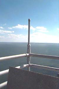
Figure 5
communications antennas, etc.), the design needed to be simple, light
weight, electrically efficient and very effective. Figure 5 illustrates
the small work area, including the access hatch and safety railing and
Figure 6 illustrates the red obstruction beacon located in the center.
It can't be seen in the photo, but the beacon lense in Figure 6 is
deformed
from the intense heat generated by the attachment channel. Both
Figures
5 and 6 were taken before the upgrade work to the top of the towers was
begun.
The attachment process must overcome the insulating properties of
air
and ionize the air to facilitate electron flow. The magnitude of the
transfer
of energy creates very high temperature. In the main channel, currents
develop temperatures 5 times that on the surface of the sun; 55,000
degrees
F.
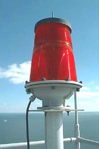
Figure 6
Attachment "leader" currents are much lower than main channel currents
and the temperatures are proportionally lower, however, it remains
apparent
that the temperatures are sufficient to cause the obstruction beacon
lense
glass in Figure 6 to soften without actually making contact with the
beacon.
This becomes more impressive when you understand that the average
attachment
and subsequent high temperature exists for less than a second.
Temperature
over time is required to increase the temperature of a material object.
When the time duration becomes very small, greater instantaneous energy
is required to do the same work. This leads into the next design
consideration;
the forcing function.
The forcing function is a statistical distribution based on the
normal
or natural "bell-curve" distribution. The nominal for Florida is
modeled
for 60,000 Amperes. The nominal for the US varies from 10,000 to 20,000
Amperes depending on who you talk to . What is really important is the
rise time. The rise time used in this model is based on the Institute
of
Electrical and Electronic Engineers (IEEE) "8x20" standard which is
found
in the IEEE Standard C-62. The standard waveform rises to maximum
current
in 8 microseconds and decays to 50% of the maximum in 20 milliseconds,
hence the nickname 8x20. This is the one most important consideration
when
designing the circuits required to handle the enormous currents
produced
by lightning.
Finally, the location as alluded to above is also a design
consideration.
The system performance in areas where nominal lightning currents are
10,000
Amperes rather than 60,000 Amperes requires a design of lesser degree
to
produce acceptable results. This equates to a lesser cost and therefore
must be a design consideration. Although steel and wood structures are
beyond the scope of this article, material is also a consideration.
Expectations
of performance such as that of steel being better than wood or concrete
is risky and may not be correct if other factors effect the performance
of the material to conduct lightning current. Geometry is the key to
optimizing
performance of any lightning protection system; site geometry,
structure
geometry, path geometry and conductor geometry.
One design consideration did not come from the upgrade design but
came
from the testing of the installed system. It was found that physically
connecting the flat strap to the steel reinforced concrete did not
cause
lightning current energy to be dissipated into the concrete. A
university
research team tested the installation and concluded that the material
difference
between the concrete and the conductor created a electron barrier
similar
to that created by a copper strip laminated to a fiber circuit board.
The
fast rise time of the current simply traveled down the efficient
conductor
and did not find the material barrier an efficient path to ground.
Advances in lightning research conducted in the last 15 years has
produced
important information that the lightning protection design engineer can
use to better design a lightning protection system. The
capabilities
of the desktop computer workstations available to the engineer allow
modeling
complex models that could only be done on a super computer a few years
ago. It can be now shown that through modeling and competent
design
that statements such as "attachments is an act of God but damage to
your
structure or equipment is due to inadequate design of your lightning
protection
system" is an expected rather than exceptional design goal. Flat strap,
Ufer grounds and path geometry are best addressed before construction
begins
and must be incorporated in the design of the structure and facility
resources.
Structure design material should be considered when designing to
reduce
lightning damage. Although there is no research proof that epoxy coated
reinforcing bar has cause lighting induced damage, there is a
hypothesis
that the use of epoxy coated reinforcing bar in concrete may case
concrete
"popping" due to induced currents from lightning. The hypothesis is
that
the epoxy coating will insulate the metal from the concrete prevent
contiguous
continuity throughout the reinforcing steel. Isolated lengths of metal
bars can resonate to the induced currents from a lightning discharge if
the length of the bar is integral multiples of the wavelength of a
lightning
discharge. This hypothesis is consistent with verified induced damage
through
copper wire which is a major issue with telephone companies and long
distance
carriers as well as power utilities. The use of fiber has been
justified
to a large extent because there is no copper in the fiber cable to
facilitate
the induction of transients from lightning.
Ultimately, the choice will be to protect for lightning damage in
the
original design or try to install lightning protection later. The
second
choice is always more expensive. From my experience, I have found that
the average lightning protection system will cost anywhere from 2 to 10
times less than the cost to install the equivalent system later.
Unfortunately,
later will not allow for the addition of Ufer grounds in the concrete
foundations
and the Ufer ground is a key consideration for tall and vulnerable
structures
and facilities.
Robert L. Gottschalk is an Electrical Engineer and Florida
Registered
Professional Engineer. Bob retired from the Florida DOT as an
Intelligent Transportation
System (ITS) Engineer Administrator and responsible for statewide
lightning
protection designs for structures and telecommunications facilities,
including
the statewide microwave radio system infrastructure that supports ITS
communications
and the statewide Motorist Aid Call Box System (MAS). Bob is now
working as a private consultant and can be reached at (850)656-2582
(voice), (850)656-4799 (fax) or by email at
r.l.gottschalk@ieee.org.